Tooling Around the Matheson History Museum
  • Blog
  • About
  • Contact
  • New Page

Braces: Part I

7/28/2015

0 Comments

 
By Donald Albury.
I was pleased to learn this week that the Tools and Hardware section of the Collectors Weekly web site has linked to this blog as a Great Reference Site.
A Brief Note on Augers
I could say that the search for truth is unending, but that seems a bit pretentious when talking about old tools. I have found, less than a week after my last post, more information about the history of augers. D.B. Laney posted a few days ago about the book Country Furniture by Aldren Watson. I've had a copy of the book for 40 years, but hadn't looked at it in a long time. I agree with Laney, this book is a real pleasure to browse through. Watson does mention (page 97) that a single cutter spiral auger with a gimlet point was invented about 1770, but the gimlet point was narrow and frequently broke. The 1809 patent that I referred to last week was apparently for the double cutting edge on a spiral auger, rather than for the gimlet point. Another source I just found on Wikisource is the article on "Boring" in the 1879 issue of The American Cyclopedia. Figures 7 through 16 illustrate the various forms of augers and auger bits in use up to that year.
Braces: Origins, Sheffield and Spofford
This issue of my blog begins a description of the braces held in the Tison Tool Barn. I will finish this topic next week.
A brace or bitstock is a woodworking tool used to bore holes in wood. It has a U-shaped section offset from the shaft of the handle that forms a crank. One end holds a bit, which will bore into wood when it is turned. The crank allows the woodworker to rotate the handle with one hand while pushing down on a knob or pad (the head) at the end of the brace with the other hand, imparting a continuous rotary motion to the cutting end of the bit. The sweep is the diameter of the circle swept out by the crank handle as it is turned. The wider the sweep, the greater the torque that can be generated with the brace.
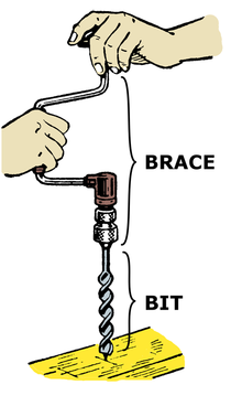
Picture
Late 19th century/20th century brace. Illustration from Pearson Scott Foresman, via Wikimedia Commons.
A brace and set of bits were essential to woodworkers well into the 20th century, but have been largely replaced by power drills. I bought a brace and set of auger bits some 50 years ago, but have not used the auger bits for 35 years. I have used the brace with a screwdriver bit on occasion. 
The brace is a relatively recent addition to the woodworker's tool chest. The oldest known surviving brace was found on the Mary Rose, an English warship that sank in 1545. The first known depiction of a brace is in a painting by Robert Campin completed sometime between 1425 and 1428. In the detail below, St. Joseph is holding the brace in an awkward manner that makes me suspect that neither Campin nor his model had ever seen a brace in use.
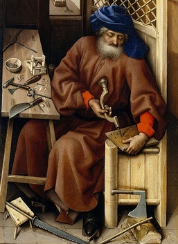
Picture
Detail from the Mérode Altarpiece by Robert Campin, via Wikimedia Commons.
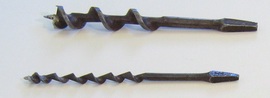
The earliest braces had a bit permanently mounted to the brace. A woodworker would need a different brace for every size hole he wanted to bore. Eventually a socket was introduced into the end of a brace, in which a wooden pad mounted to a bit was held by friction, or by a thumbscrew. The sockets and pads had a square cross-section. Some early sockets and pads had the same width for their full length, but the development of tapered pads and sockets allowed for easier insertion and removal of bits while still achieving a tight fit. Wooden pads for bits were eliminated by the development of tangs, in which bits were given a tapered end with a square cross-section. 
Picture
Bits with tapered tangs with a square cross-section. Detail of photo by Johan, via Wikimedia Commons.
A mechanical device to secure the tang of a bit to a brace is called a chuck. There have been many types of chucks and many styles of braces in the past two centuries. I will only cover ones for which examples are found in the Tison Tool Barn.
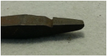
One early method of securing bits to a brace was the cut-tang chuck, in which the tang has a slot which is engaged by a spring-loaded hook. 
Picture
Tang with slot for use in a cut-tang chuck. Photo by Donald Albury.
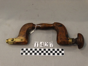
The brace shown below is a Sheffield-type brace with a push-button chuck. A push-button chuck is a type of cut-tang chuck. The button pushes the hook clear, releasing the bit. There are no markings on this brace. A book on 18th century tools published in 1816 has an illustration showing a brace with a push-button chuck. Similar braces were made through most of the 19th century. The brace is 13.5 inches long, and the crank has a 7 inch sweep.
Picture
Sheffield style brace with push-button chuck, no reinforcing places. Photo by Donald Albury.
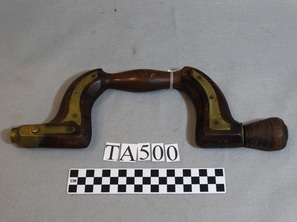
The next brace is another Sheffield style brace with a push-button chuck. This brace has brass (or brass-plated) reinforcing plates attached to the curved sections of the brace. The only markings on the brace are the name "JOHN GREEN" with unevenly spaced and aligned letters, and "1816" in another location. "John Green" is probably an owner's name. The number is a problem. I doubt an owner would bother to stamp a date on his tool. A manufacturer might stamp a part number on a tool, but that is seen primarily on metal tools. A year may appear on a tool as either the date the manufacturer was founded, or the date a patent was issued, but neither is the case here. I suspect the "1816" was added at some point to make the tool seem older, and therefore more valuable. The brace is 11 inches long and has an 8 inch sweep.
Picture
Shefffield style brace with push-button chuck and brass reinforcing plates. Photo by Donald Albury.
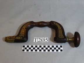
The brace below is a Sheffield style brace with a lever release chuck. This is another type of cut-tang chuck, in which pressing the lever lifts the hook out of the slot on the tang. It has brass reinforcing plates on the curved parts of the brace. It is stamped "Made for T. TILLOTSON SHEFFIELD". Thomas Tillotson was a merchant and dealer in New York. The business, an old family firm, became "T. Tillotson" after 1843, when Thomas's brother John left the firm, and appears to have closed by the beginning of the Civil War. This leaves a well defined time period in which the brace was probably produced. The brace is 14 inches long, and the crank has a sweep of 7 inches.
Picture
Sheffield style brace with lever release chuck and brass reinforcing plates. Photo by Donald Albury.
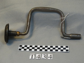
This next brace is a steel brace (even the head is metal). It has a Taylors Patent chuck, which is another type of cut-tang chuck. Jeremy Taylor of Connecticut patented this chuck in 1836. The brace is also marked "I. WILSON". Increase Wilson manufactured tools starting in 1818. His business became a public company under the name "Wilson Manufacturing Co." in 1855. This brace is 12 inches long, and the crank has a 9 inch sweep.
Picture
Steel brace with a Taylors Patent chuck. Photo by Donald Albury.
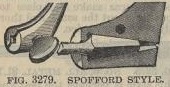
In 1859 Nelson Spofford received a patent for a "clamshell" type of chuck. This chuck was formed by a fork or split at the end of the brace, with a channel for a bit tang. The chuck was closed on the tang like a vise by turning a thumbscrew. The Spofford chuck was used starting in 1859 on braces produced initially by Fray & Pigg Manufacturers, and from sometime before 1866 by John S. Fray and Co. Stanley Works acquired John S. Fray & Co. shortly after 1900 and continued to manufacture Spofford chuck braces until 1942. 
Picture
Cutaway drawing of Spofford style chuck. Detail from 1897 catalog from Charles A. Strelinger & Co.
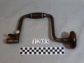
The brace below has a Spofford chuck. It is marked "JOHN S. FRAY" and "BRIDGEPORT, CT." The wood head and rotating wood grip on the crank indicates that this is a later model from Fray. The wood crank grip is two parts held together on the crank by pewter rings. The brace is 11.75 inches long, and has a sweep of 13 inches.
Picture
Brace with a Spofford chuck. Photo by Donald Albury.
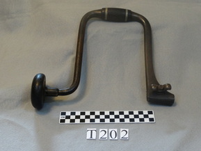
This next brace is not marked, but is very similar to the one above, and likely also from John S. Fray & Co. It also has a wood head and crank grip, and is therefore from sometime in the later part of the 19th century or the 20th century. The brace is 11.5 inches long and has a 17 inch sweep.
Picture
Brace with Spofford chuck. Photo by Donald Albury.
I will cover more braces from the Tison Tool Barn next week.
Sources:

Hand-powered drilling tools and machines, Low-Tech Magazine
A Collection of Bit Braces
Brace Innovative History: an Overview
The Primitive Wooden Brace
Repair of push-button chuck
John S. Fray & Co.
Spofford Style Braces
PEXTO Braces
Barlow, Ronald S. (1999) The Antique Tool collector's Guide to Value. Gas City, IN: L-W Book Sales.

Another source (for information about all sorts of old hand tools) is:
Walsh, Peter C., Woodworking Tools 1600-1900, Smithsonian Institution. The e-book version is downloadable for free from Project Gutenberg. Information about augers is found starting at location 515.
0 Comments

Augers and Gimlets

7/22/2015

2 Comments

 
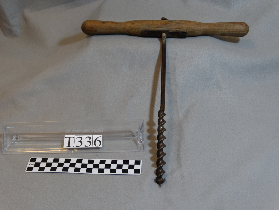
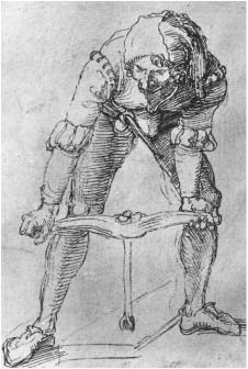
Augers and gimlets are tools used to bore holes in wood. They consist of a metal bit that digs out wood when it is rotated, and a handle, usually wood, mounted on the far end that is turned by hand. The primary difference between augers and gimlets is size: augers require two hands to turn, while gimlets need only one hand.
Picture
Man with an Auger, by Albrecht Dürer, ca 1496, via Wikimedia Commons
The augers I'll write about here are woodworking tools used by themselves, sometimes called T-augers because the handles are set perpendicular to the shaft. I will cover woodworking auger bits, which are used with a brace or drill, in a future post. Other types of augers include earth augers, grain augers, coal augers, mine augers, and ice augers, but the Tison Tool Barn does not have any examples of those types of augers. 

Besides boring holes for pegs, or more recently, bolts, augers are also used to remove much of the waste wood from rectangular holes, such as mortises. Gimlets are often used for pre-drilling nail and screw holes. A woodworker would need a set of augers and gimlets in various sizes. As the handles are fixed, the woodworker would also need a lot of storage space.
Early augers were of the spoon, pod, or shell type, with a half cylinder forming the cutting part, tapering to a rounded point on the end, on a shaft extending to the handle. Spoon augers are known from more than a thousand years ago, and perhaps were used as long ago as classical times (2,000 or so years ago). The Viking-age Mästermyr chest that I mentioned last week held a number of spoon augers.
Picture
Spoon auger. Photo by Jens Mohr, via Wikimedia.
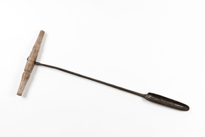
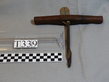
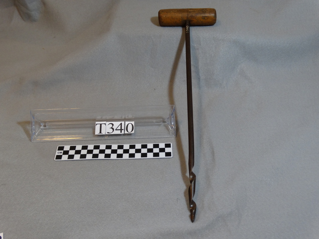
Spoon augers require a starting hole, made by a chisel or other cutting tool. Another disadvantage of spoon augers is that chips and shavings accumulate in the hole, and the auger has to be periodically withdrawn to clear the hole. The Tison Tool Barn does not hold any examples of plain spoon augers. It does have an auger, shown below, that appears to be a twisted spoon auger with a conical screw point, also known as a gimlet point. The screw point, which is found on all of the augers and gimlets in the Tison Tool Barn, allows the auger to start its own hole, and helps pull the auger into the wood as it is cutting a hole. This auger bores a hole 1/2 inch in diameter. The shaft is 7 inches long and the handle is 8 1/2 inches across.
Picture
Photo by Donald Albury.
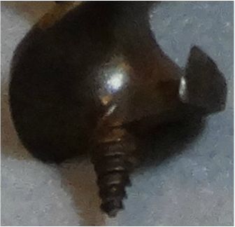
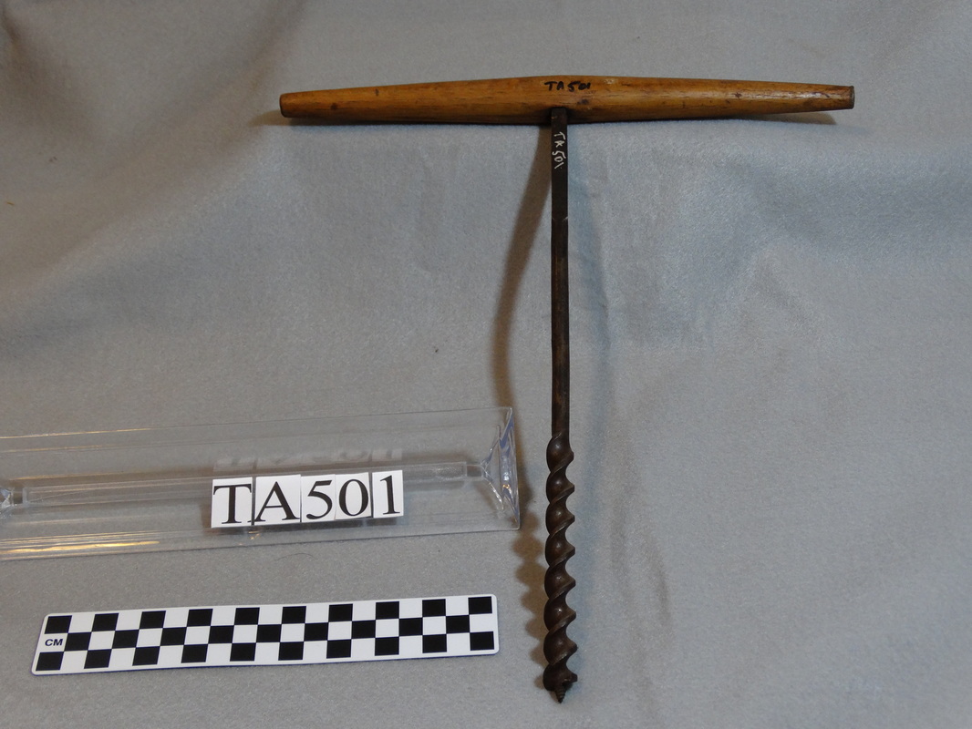
Spoon augers were eventually replaced by twist or screw augers. A screw auger has the form of an Archimedes' screw, with a helical surface extending about one-half of the length of the auger. The bottom of the helix has a cutting edge which shaves wood from the bottom of the hole as the auger is turned. The helical surface lifts the waste wood up and out of the hole. A typical screw auger, as in the detail view below, has a conical screw point on the end, which helps center the auger as the hole is started, and draws the auger into the wood. It also has spurs at the outside edge of the cutting blade to cut wood fibers and permit the shavings to be lifted up without tearing the wood. The screw auger may have been invented in the 18th century, but did not come into wide use until the 19th century. The conical screw point, or gimlet point, on an auger was patented in 1809.
Picture
Photo by Donald Albury.
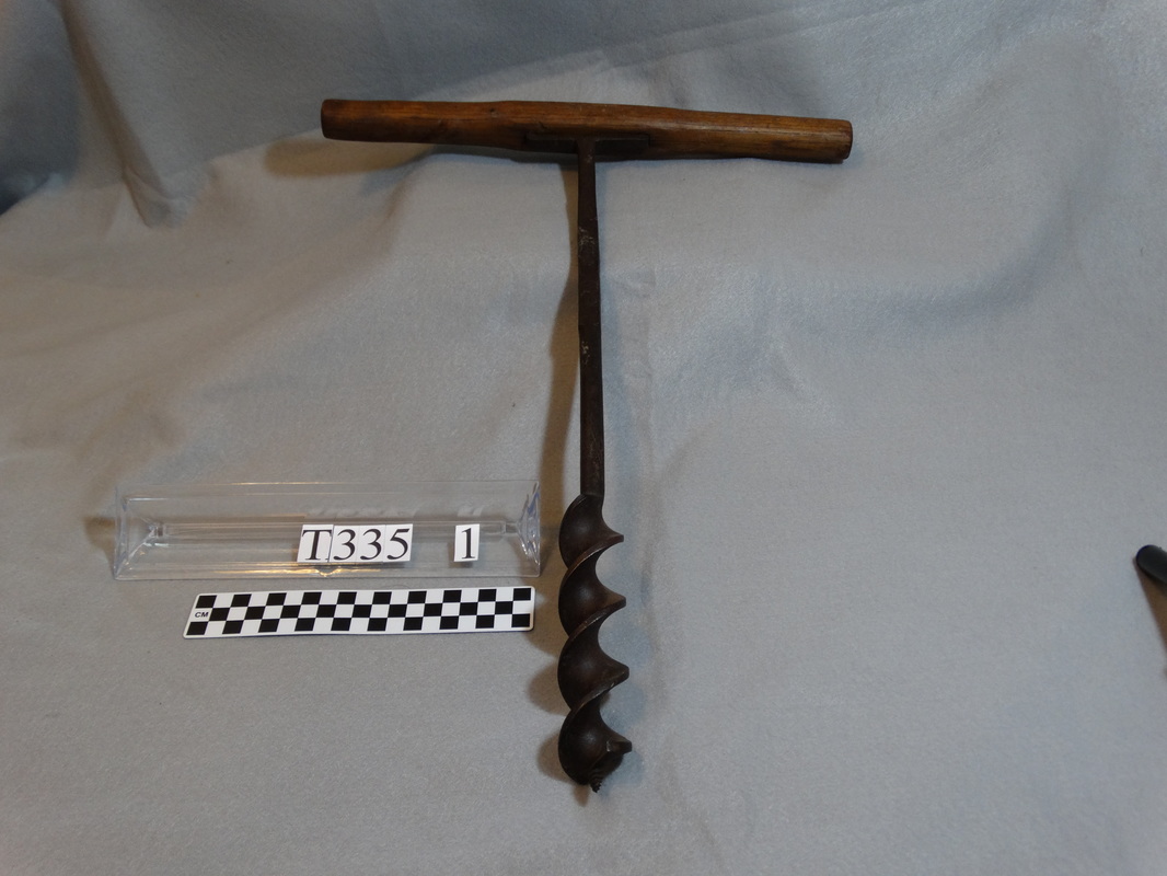
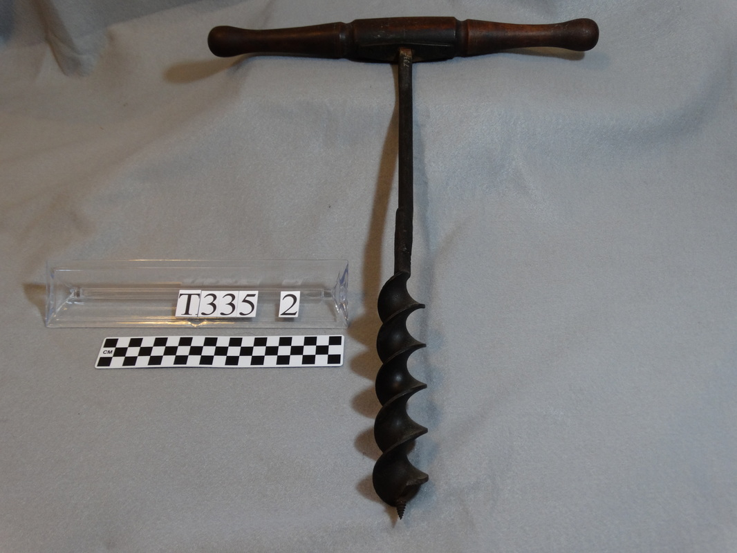
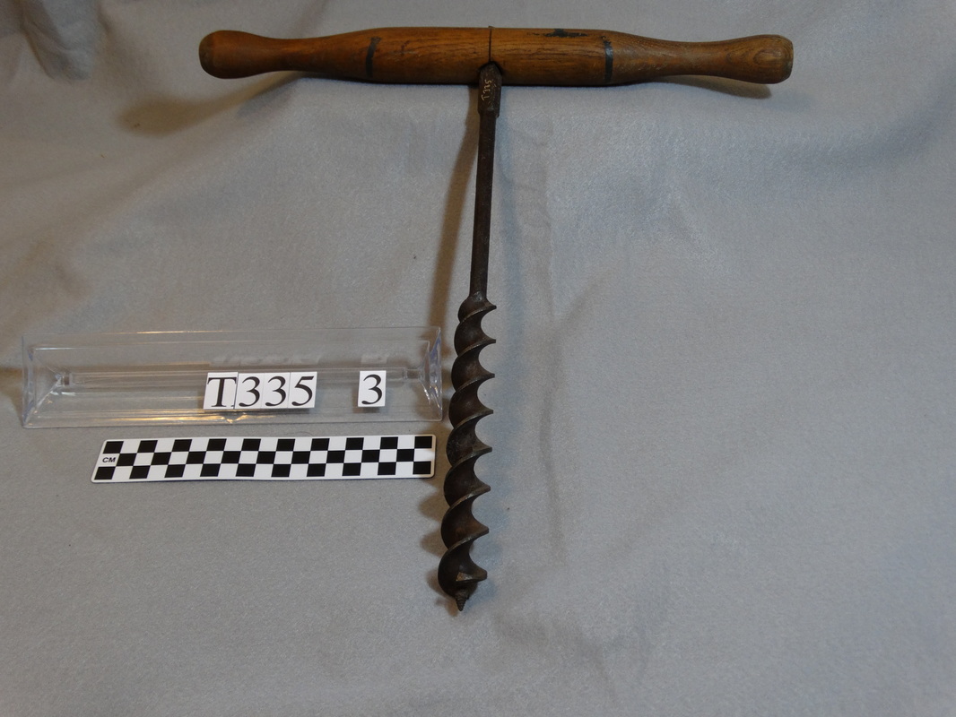
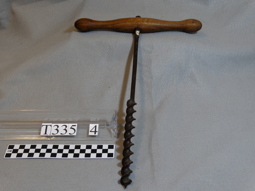
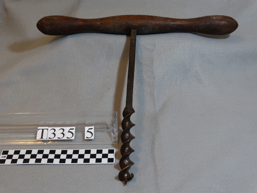
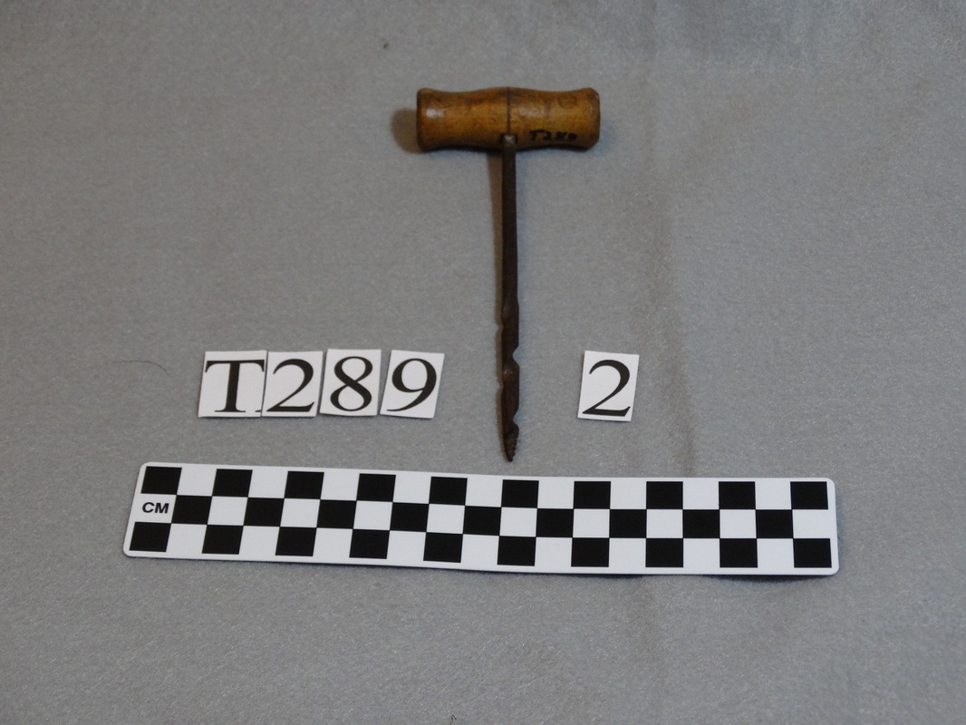
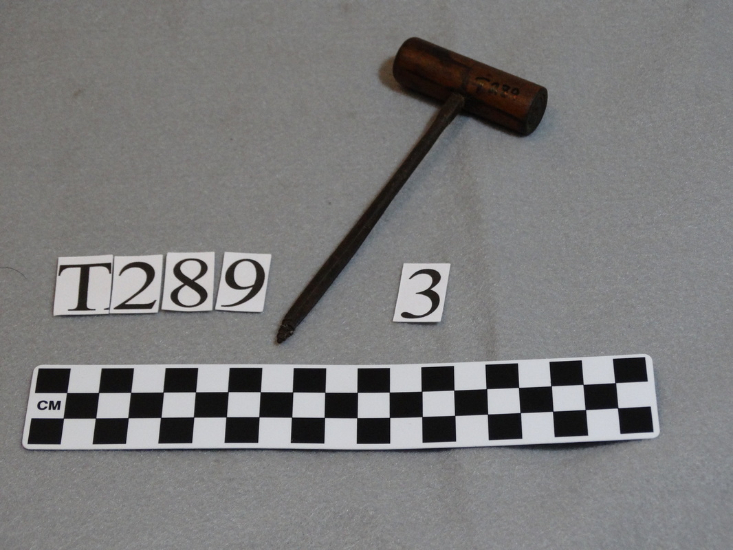
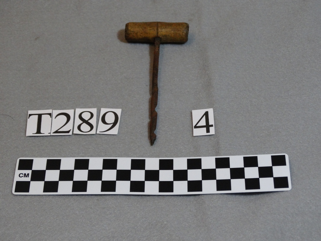
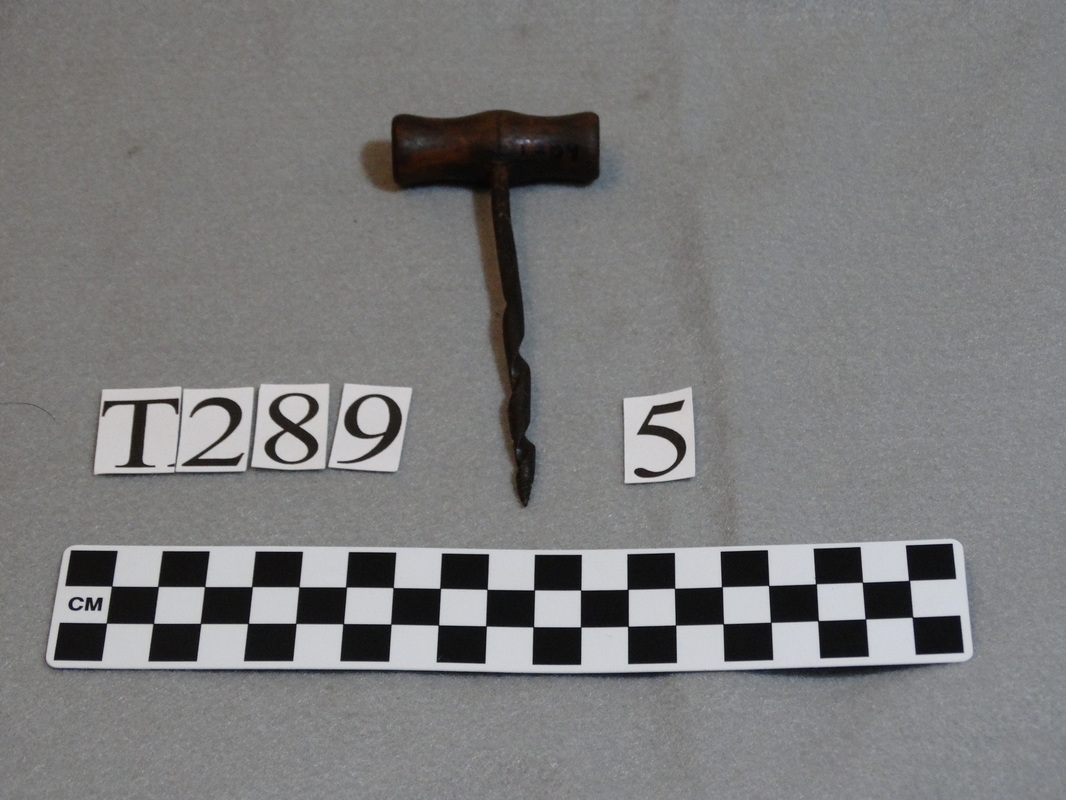
The Tison Tool Barn has several screw augers, shown below. They bore holes that range from 9/16 inch to 1 1/2 inches in diameter.
Photos by Donald Albury.
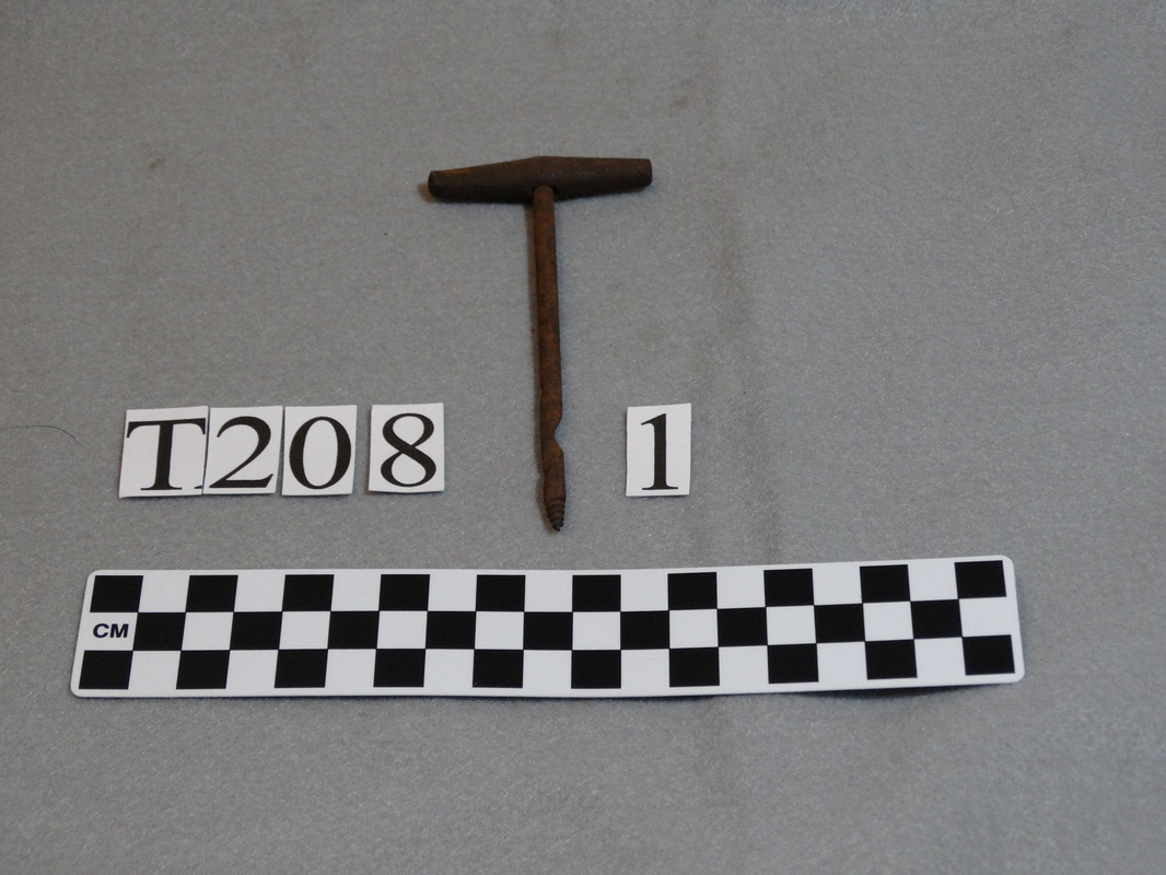
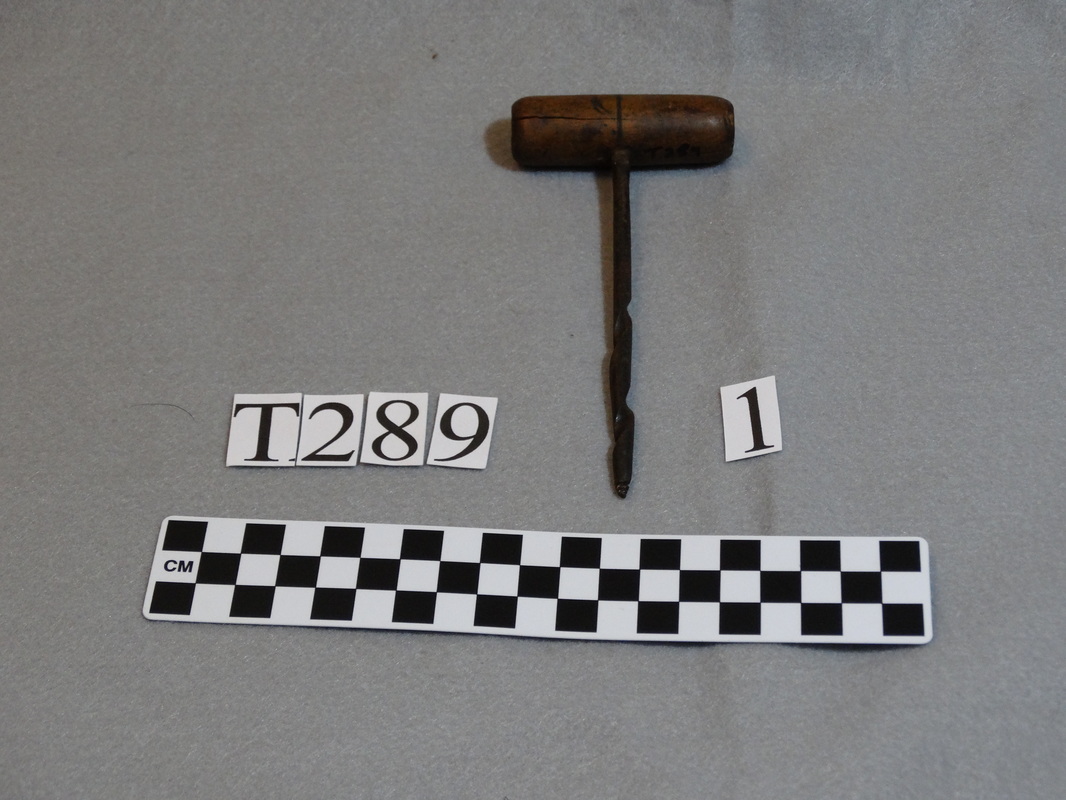
The Tison Tool Barn also has several gimlets, shown below. All of the gimlets in the Tool Barn are of the spoon or twisted spoon type and have conical screw points like those on the screw augers in the Tool Barn. They bore holes that range from 3/32 to 3/8 inch in diameter.
Photos by Donald Albury.
I have not found a comprehensive history of augers and gimlets on the Internet, but a few short bits of information are at:
Augers, Gimlets, and Braces, at Colonial Williamsburg
The Mästermyr Find, page 13
Auger, in Encyclopedia Britannica
Spoon auger - a carpenter's tool (BBC)

Another source (for information about all sorts of old hand tools) is:
Walsh, Peter C., Woodworking Tools 1600-1900, Smithsonian Institution. The e-book version is downloadable for free from Project Gutenberg. Information about augers is found starting at location 515.
2 Comments

Drawknives

7/15/2015

0 Comments

 
Drawknives
By Donald Albury
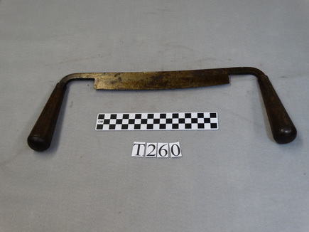
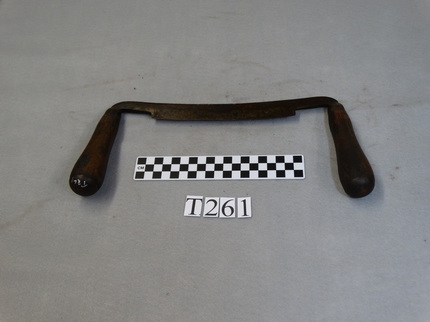
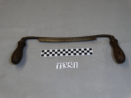
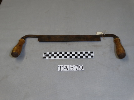
Drawknives, also known as drawing knives, draw shaves, or shaving knives, are tools used to shape wood. As the first three names suggest, drawknives are drawn, or pulled, towards the worker. As the last two names suggest, drawknives remove shavings from wood. A drawknife consists of a long narrow blade with projections at each end fitted with handles. One long edge of the blade is sharpened. In many woodworking traditions, including English and American, the wooden handles usually are on tangs set at a more or less right angle to the axis of the blade and extend more or less parallel with blade toward the side of the blade that is sharpened. French drawknive handles often also are at a right angle to the blade, but have very short handles, while Swedish, Japanese and some German, Austrian and Swiss drawknives have handles that extend straight out from the ends of the blade. The length of the blade, the curvature of the edge, and the curvature of the flat of the blade may all vary. The drawknife has had many uses, including removing bark from logs, rough shaping of boards, rounding pieces of wood for later finishing on a lathe, making tool handles and fence posts, preparing horse's' hooves for shoeing, and carving compound curved surfaces such as chair seats and the interior of bowls.
Picture
Typical drawknife partway through removing a shaving. Photo by Simon A. Eugster, via Wikimedia Commons.
There is little evidence on the early history of drawknives. Ancient drawknives are very rare. A remarkable find was the Viking-age Mästermyr chest, which contained many tools and other items, including an inshave or two-handled scorp (a specialized type of drawknife). References to drawknives in art or writing before the 18th century are also rare. The first use of the term "draweing-knife" recorded in the Oxford English Dictionary was in 1645. The OED also has a quote from 1679 describing the use of the tool: "With the Handles of the Draw-knife in both their hands, enter the edge of the Draw-knife into the Work, and draw Chips almost the length of their work." With the development of mass production of tools in the 19th century, many drawknives were acquired by people who made only occasional use of them. As more household and farm items, such as tool handles, chairs, and such were store-bought instead of home-made, tools like drawknives were used less often, and many from the 19th and 20th centuries have survived. The Tison Tool Barn has several of these drawknives. First I will list the standard drawknives in the collection.
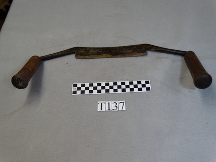
The drawknife below is marked "D. R. BARTON ROCHESTER". The cutting edge is 7 5/8 inches long. D. R. Barton began manufacturing edged tools in 1832. The name remained in use until 1939. D. R. Barton tools had a reputation for high quality.
Picture
Photo by Donald Albury.
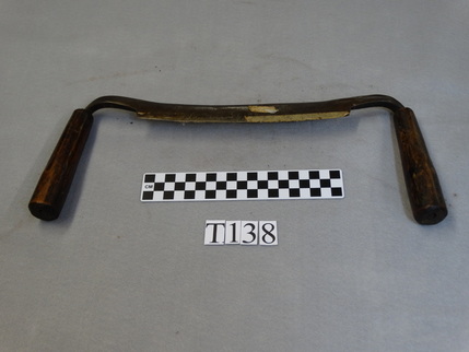
The next drawknife has no discernible markings on it. The blade edge is 8 1/8 inches long. The light colored areas on the blade are pieces of old masking tape, which are difficult to remove without scratching the metal.
Picture
Photo by Donald Albury.
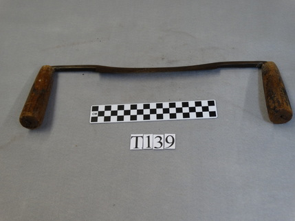
This drawknife is marked "STEPHENSON". Unfortunately, I have not been able to identify what this name signifies. The blade edge is 7 3/4 inches long.
Picture
Photo by Donald Albury.
The next drawknife is marked "~~ CROSSMAN 9" (the first part is unreadable) and "CAST STEEL". A. W. Crossman & Co. of Warren, Massachusetts manufactured cast steel tools from about 1850 until sometime after 1870. The company seems to have been known mainly for making chisels and slicks. The edge of the blade is 9 inches long.
Picture
Photo by Donald Albury.
The next drawknife is marked "T. ~ WITHERBY 7" (the second letter is unreadable). T. H. Witherby of Millbury, Massachusetts began making chisels in 1827. Witherby's company was later acquired by the Winsted Edge Tool Works, which continued use of the Witherby brand until 1955. Witherby brand tools had a high reputation for quality. The form of the name stamped on this drawknife appears to have been in use from 1882 to 1919. Although the tool has a '7' stamped on it, the blade edge is just 6 1/2 inches long.
Picture
Photo by Donald Albury.
The next drawknife has only "9 IN" stamped on it. The edge of the blade is 9 inches long. 
Picture
Photo by Donald Albury.
The drawknife below has a logo stamped on it, "PEXTO" inside an oval, followed by "10". The logo was for the Peck, Stow & Wilcox Co., and was first used in 1914. The PEXTO name is still used by Roper Whitney for metal fabrication equipment. The blade edge is 10 inches long. I initially read the final letter in the logo as "D". This seems to be an easy mistake to make, as I have found a number of tools on auction sites on the Internet listing them as made by the "PEXTD" company.
Picture
Photo by Donald Albury.
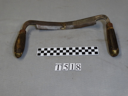
The next drawknife has no markings. The blade has been bent in two places, seriously cracking the metal. Someone tried to repair the blade by filling in the cracks with a bronze-colored metal, but voids remain along the cracks. I suspect someone tried to convert this drawknife to an inshave. The blade edge is 8 3/8 inches long.
Picture
Photo by Donald Albury.
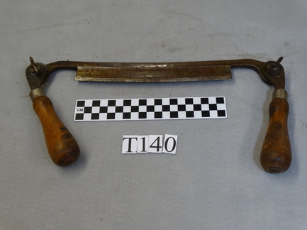
The drawknife below has folding handles, secured in the desired position by wingnuts. When folded, the handles protect the edge of the blade, and make the tool more compact for storage. The drawknive is marked "JENNINGS" and "PAT PEND", and with a "J" inside an upward pointing arrowhead with the base open. The "J" in an arrowhead was trademarked by Charles. E. Jennings & Co. The company was in business from 1873 until 1923. A patent on this tool was issued to Jennings in 1906. This indicates that the tool was made no later than 1906. As I don't know what the backlog for issuing patents was at the time, I can't say how much earlier than 1906 it may have been made. The edge of the blade is 8 1/8 inches long.
Picture
Photo by Donald Albury.
The drawknife below also has folding handles secured by wingnuts. The wooden handles have notches, allowing the handles to enclose the blade when folded. The drawknife is marked "A. J. WILKINSON & CO.", "MAKERS BOSTON, MASS" and "PATENTED JULY 16, 1895". A. J. Wilkinson & Co. manufactured tools from 1842 to 1993. They were noted for their folding drawknives. The edge of the blade is 8 inches long.
Picture
Photo by Donald Albury.
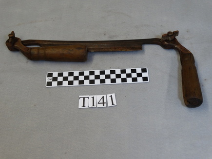
The next drawknife has adjustable handles. The handles originally could pivot around the long axis of the blade, and be locked into position. The mechanisms are rusted in place. There are no markings on the tool. The blade edge is 11 3/4 inches long.
Picture
Photo by Donald Albury.
Shown below is the cooper's hollowing drawknife I wrote about two weeks ago. The tools has no markings. The blade edge is 6 3/16 inches long.
Picture
Photo by Donald Albury.
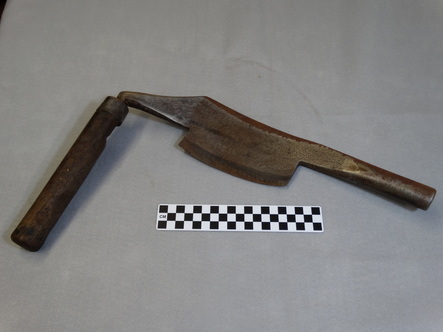
We now come to some specialized variants of drawknives. The next drawknife is the cooper's champer knife that I wrote about last week. Note the asymmetrical handles that distinguish this tool.
Picture
Photo by Donald Albury.
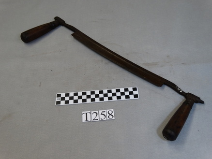
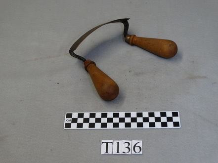
The final tool in this week's post is an inshave or two-handled scorp. This tool has a moderate curve in the blade, but the handles are set close to each other, at a distance shorter than the length of the blade. (A one-handled scorp has a much more sharply curved blade, with the tangs at the ends of the blade meeting at a single handle.) This design allows an inshave to be used in an enclosed space, such as inside a bowl.
Picture
Photo by Donald Albury.
Drawknives continue to be manufactured and even crafted by hand, but their use is confined to hobbyists and a very limited number of craftsmen.

Sites of interest:
A Woodworkers Musings
Drawknife (in Wikipedia)
Glossary Drawknife
All photographs by Donald Albury in this blog are licensed under a Creative Commons Attribution-ShareAlike 4.0 International License.
0 Comments

Fitting a Cask Head

7/8/2015

2 Comments


By Donald Albury

I wrote in the last post in this series about how coopers shaped staves. After assembling the staves with hoops, the cooper smoothed the inside and outside of the container. I will again pass over how that was done since the Tison Tool Barn does not have examples of the tools used. Finally, the cooper finished both ends of a cask or single-bottom container.
At this point the ends of the staves were uneven. The cooper leveled the ends of the staves, often using a hand adze. The Tison Tool Barn has an example of a cooper's hand adze.
Picture
Cooper's hand adze in the Tison Tool Barn. Photo by Donald Albury.
Next, the cooper used a sun plane (also known as a leveling or topping plane) to smooth the ends of the staves. The sun plane is a curved jointer plane. The curve allowed all of the plane to be supported by the ends of the staves as the cooper pushed it around the end of the container. The Tison Tool Barn has an example of a sun plane, which unfortunately is missing its iron and wedge.
Picture
Cooper's sun plane (missing iron and wedge) in the Tison Tool Barn. Photo by Donald Albury.
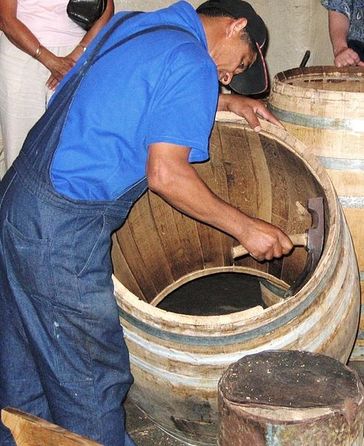
The cooper might next use his hand adze to cut the chime, a bevel or chamfer, on the inside edge of the end of the container. The chime prevented the inside edge of the end of a stave from splitting away when pressure was put on it.
Picture
Cooper cutting the chime around the inside of the end of a barrel using a hand adze. Photo by Dewet, via Wikimedia Commons.
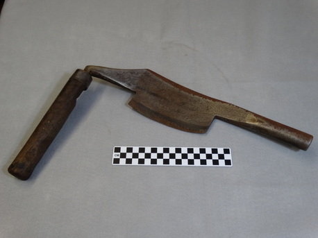
Whether or not the cooper had started the chime with an adze, he would use a champer knife to finish it. One of the quirks of traditional names for tools is that a cooper uses a chamPer knife to cut a chamFer. You can find links to "chamfer knives" on the Internet, but "champer" appears to be the older form. The Tison Tool Barn has an example of a cooper's champer knife.
Picture
Cooper's champer knive in Tison Tool Barn. Photo by Donald Albury.
Next, the cooper would cut a howell or chiv around the inside of the container below the chime using a howell gouge plane. The howell is the shallow depression running around the inside of the barrel in the picture below.
Picture
Open end of a barrel showing the chime on the end, the howell just below it, and the croze groove running around the deepest part of the howell. Photo by Olivier Colas, via Wikimedia Commons.
The Tison Tool Barn has two howell gouge planes. One of the planes has a straight iron with a rounded profile at the end, which cuts the howell with the desired profile. The other plane has an iron that curls up, so that one side of the iron cuts the howell. The two planes have different radii of curvature, matching casks with different diameters at the head. I have also seen a photo of two sun planes together, in which it is obvious that they have different radii of curvature. This is a bit of a mystery to me. I have not found any reference to different radii of curvature for sun planes, howell gouge planes, or croze planes, yet it makes sense to me that, at least for howell gouge planes, a plane that fits the curvature of the end of the cask would yield a smoother and more uniform howell.
Two howell gouge planes in the Tison Tool Barn. Photos by Donald Albury.
The head of a cask or a single-bottom container (bucket, etc.) is formed by boards held together edge-to-edge by dowels and cut in a circle. The edge of the head is beveled on both sides all the way around. The croze is a groove cut around the container in the deepest part of the howell. When the head is installed, its beveled edge fits into the croze. The hoop on the end of the container has to be temporarily loosened, allowing the ends of the staves to move outward while the head is forced into position, and then tightened again to secure the head. The croze is cut by a croze plane.
There are several types of croze plane. The Tison Tool Barn has a sliding post type croze plane with a saw-tooth iron. The iron is set parallel to the line of the croze around the inside of the cask, and cuts a square-sided groove (some croze planes cut a V-shaped groove, and are therefore called 'V-croze planes'). This tool came to the Tison Tool Barn labeled as a barrel or cooper's plane.
Picture
Cooper's croze plane in the Tison Tool Barn. Photo by Donald Albury.
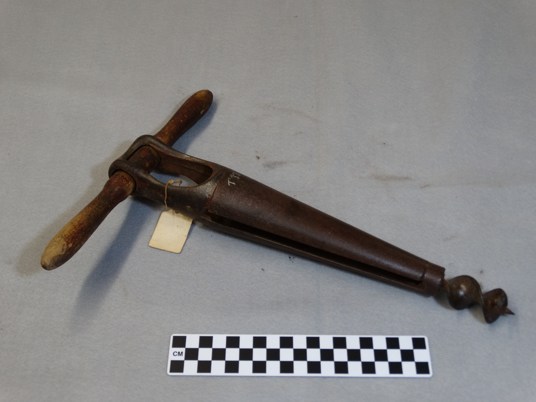
A cask that is used to distribute liquids such as beer, wine or liquor has a tap hole near the edge of the head in one end. During transportation and storage the tap hole is closed with a stopper. When the cask is to be used to dispense drinks, the stopper is removed and a tap inserted into the tap hole. Casks holding liquids also have a bung hole in one stave at or near the bilge (the widest part) of the cask. The bung hole allows the cask to be filled or topped up without removing a head. When casks are used to age beer, wine or liquor, the bung hole serves as an inspection port, allowing the liquid to be tested for quality without using a tap or disturbing the cask. Tap holes and bung holes are bored before final assembly of the cask. After all, people might object to sawdust and wood shavings floating in their drink. Tap holes and bung holes are tapered, as are plugs and tap stems. The Tison Tool Barn has a tap hole auger and a bung hole borer.
The tap hole auger on the left was probably used with a brace. The bung hole borer on the right cuts a larger hole. Both tools are in the Tison Tool Barn. Photos by Donald Albury.
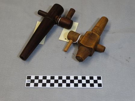
The Tison Tool Barn also has two taps. 
Picture
Two wooden taps in the Tison Tool Barn. Photo by Donald Albury.
The Coca-Cola® syrup cask pictured in the post two weeks ago specified on the label that only a wooden tap was to be used to draw syrup from the cask.
Next week I will write about drawknives
Disclaimer: I did not know anything about coopering until I became curious about the cooper's tools in the Tison Tool Barn. I have researched the subject on the Internet and found tantalizing hints, speculation, contradictions, blurry images of old books, and what I hope is relatively reliable, if incomplete, information. I have tried to hold my own speculation in check, even though it so much fun to speculate. I am responsible for any errors in this post. Some sources I consulted for these posts are:

'Cooper (profession)', at Wikipedia
'Barrel', at Wikipedia
The Cooper (Bedford County)
Eighteenth Century French Coopers
Making Wooden Buckets
The Newfoundland Cooper Trade
Creative Commons License
All text and photographs by Donald Albury in this blog are licensed under a Creative Commons Attribution-ShareAlike 4.0 International License.
2 Comments

Shaping Staves

7/1/2015

1 Comment


Shaping Staves

By Donald Albury
Before I get to the staves, I have a quick note on a major local use for casks that I missed last week, storing and transporting naval stores. We tend to refer to naval stores as turpentine: turpentine camps, turpentine trees, turpentine knives, turpentine cups. Until late in the 20th century, turpentine was primarily extracted from pine sap by distillation (waste wood, old stumps and such are the primary source now). The pitch or rosin left after distillation, as well as the raw gum from pine trees, were also commercially valuable. All of these products were stored and shipped in wood casks. Larger turpentine camps had a resident cooper to assemble and repair casks. I will discuss turpentine tools and related objects in the Tison Tool Barn in a future post.
Casks and single-bottom ( white-cooperage) containers are assembled from staves held in the shape of a tube by hoops. Staves are boards with beveled edges, so that when they are assembled into a tube, the edges fit squarely and tightly together. Staves in casks also taper from the middle to each end, so that when they are drawn together by hoops the ends have a smaller diameter than the middle of the cask (the bilge). A cooper had to carefully shape each stave so that all the staves would properly fit tightly together when the container was assembled.
Picture
By Gerard Prins, via Wikimedia Commons
A cooper working by himself, as in a small town, made all the wooden parts of a cask, including cutting and riving boards to be used as staves. In larger cooperages, such as in cities, boards were bought from lumber dealers, and workers often specialized in making staves. As the tools used in producing boards were not limited to coopers, I am skipping over that process. 

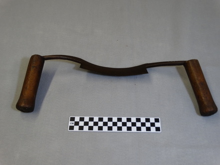
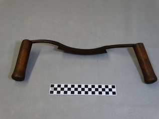
The cooper would shape staves using several tools. The cooper shaped the stave to be slightly cupped, convex on the outside face and concave on the inside face. He did this using special draw knives. The Tison Tool Barn holds an example of a cooper's hollowing draw knife, which was used to shape the concave face of the board. 
Picture
Cooper's hollowing drawknife from the collection of the Tison Tool Barn. Photo by Donald Albury.
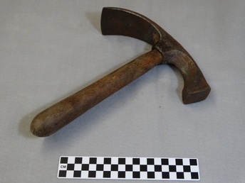
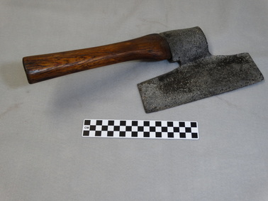
Staves for casks had to be tapered at both ends. Staves for many single-bottom containers, such as buckets, tubs, and churns, had to be tapered from one end to the other. The cooper used a side-ax to rough out the tapers. Side-axes are used to cut a flat surface on a timber or board, and have the blade offset at an angle from the handle. This protects the ax's handle (and the worker's knuckles) from hitting the wood. The cooper's side-ax has a very short handle, and is used one-handed. (Most axes have long handles and require two hands to swing.) The cooper held the stave in one hand and swung the ax with the other hand to shape the stave.

The tools in the Tison Tool Barn have come from private collections, and the Matheson History Museum has little or no information on the source and history of the tools. Individual tools may have passed through the hands of dealers and collectors who were not always aware of the intended or actual use of the tool. We cannot always rely on the names attached to such tools when they are donated to the museum. The Tison Tool Barn has a tool that has been labeled as a cooper's side-ax, but it has a three-foot long handle, and every source I have found states that a cooper's side-ax has a very short handle. The tool in the photo below has been labeled a turner's side-ax, but my search of the Internet has found only one mention of a turner's side-ax, and many references to cooper's side-axes. The tool in the Tison Tool Barn pictured below matches all the descriptions and photos of a cooper's side-ax that I have found. This tool may have had other uses, and short-handled side-axes are used today for carving wood, but the tool pictured is representative of a cooper's side-ax.
Picture
Cooper's side-axe from the collection in the Tison Tool Barn. Photo by Donald Albury.
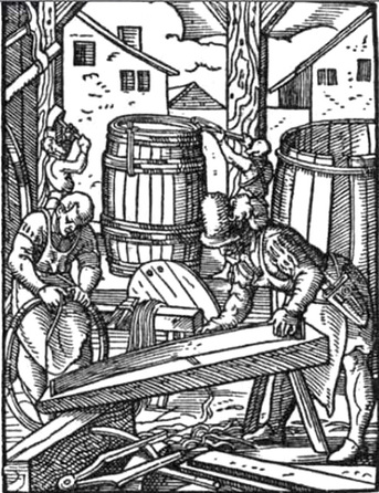
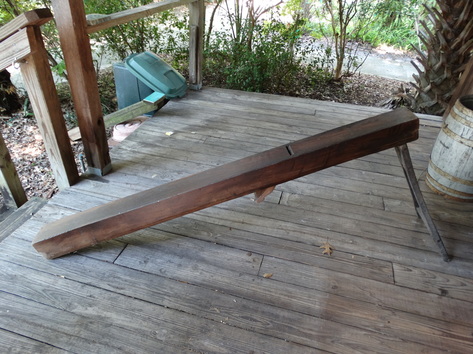
After rough-shaping a stave with an axe, a cooper had to smooth the edges of the stave with a plane. Most woodworking with planes involves holding a piece of wood in place with a vise or clamp, and pushing the plane along the surface of the wood, shaving thin sections off the wood. Due to the size and cupping of staves, and the need to bevel the edges, using a hand plane is not practical. Coopers instead used a cooper's plane, also called a long jointer plane, to finish the edges of staves. Jointer planes are the longest hand planes, up to two feet long. Cooper's planes or long jointer planes are four to more than six feet long, and are mounted upside down, so that the sole of the plane and the cutting blade (the iron) is on top. One end of a cooper's plane is supported by legs, while the other end either rests on the floor, or on a bench. The cooper would finish the edge of a stave by moving the stave along the sole of the stationary plane. 
Picture
16th century cooper shaping a stave on a cooper's plane. From Wikimedia Commons.
The Tison Tool Barn holds a cooper's long jointer plane.
Picture
Cooper's plane from the collection in the Tison Tool Barn. Photo by Donald Albury.
After the staves are finished, the cask is assembled by fitting hoops over the ends and forcing them down to draw the staves tightly together. This involves a number of steps and tools, some specialized to coopers, but the Tison Tool Barn does not have examples of those tools, so I will again pass over that process. 

After the staves are hooped, both ends of a cask and the bottom of a white-cooperage container are prepared for fitting a head (yes, a head closes a bottom, so that a single-bottomed container has one head, while a double-bottomed cask has two heads). Next week I will describe tools held in the Tison Tool Barn that were used by coopers to prepare the ends of casks and white-cooperage containers for receiving heads, and for tapping liquids stored in casks.
Disclaimer: I did not know anything about coopering until I became curious about the cooper's tools in the Tison Tool Barn. I have researched the subject on the Internet and found tantalizing hints, speculation, contradictions, blurry images of old books, and what I hope is relatively reliable, if incomplete, information. I have tried to hold my own speculation in check. I am responsible for any errors in this post. Some sources I consulted for these posts are:

'Cooper (profession)', at Wikipedia
'Barrel', at Wikipedia
The Cooper (Bedford County)
Eighteenth Century French Coopers
Making Wooden Buckets
The Newfoundland Cooper Trade
Cooper or Barrel maker (covers coopering in the turpentine industry in northern Florida)
Creative Commons License
All text and photographs by Donald Albury in this blog are licensed under a Creative Commons Attribution-ShareAlike 4.0 International License.
1 Comment

    Author

    I have been a volunteer at the Matheson History Museum. Feeling an affinity with old hand tools (some of which I remember from my youth), I have tried to learn more about the history of the tools in the Tison Tool Barn, and how they were used.

    I am not an expert on tools. I have used some of the tools represented in the Tison Tool Barn, though perhaps not very well. I do enjoy digging around to find out more about the tools, and hope that some of you share my interest in the old tools collected in the Tison Tool Barn.

    This is my personal blog. Any claims, suppositions or opinions offered here are mine, and do not necessarily represent those of the Matheson History Museum, its staff or its Board of Directors.

    All text and photographs by Donald Albury in this blog are licensed under a Creative Commons Attribution-ShareAlike 4.0 International License. All illustrations taken from Wikimedia Commons are either in the public domain, or have been released under a Creative Commons license.

    Archives

    December 2015
    November 2015
    October 2015
    September 2015
    August 2015
    July 2015
    June 2015

    RSS Feed

    Categories

    All
    Acme-wrench
    Auger
    Auger Bits
    Barnes Tool Company
    Bemis & Call
    Bicycle Wrench
    Bit Gauge
    Brace
    Center Bit
    Chuck
    Coes Wrench Co.
    Combination Wrench
    Cooper Tools
    Countersink Bit
    Crescent Wrench
    Drawknife
    Factory
    Folding Ruler
    Gimlet
    Hammer Wrench
    H. D. Smith
    Hollow Auger
    Inshave
    Lucas Girder Wrench
    Marking Gauge
    Matheson History Museum
    Miehle
    Monkey Wrench
    Peck
    Perfect Handle
    Pipe Wrench
    Reamer Bits
    Ripley's Patent Wrench
    Sheffield
    Skid Shoe
    Slide Ruler
    Spofford
    Spoke Pointer
    Stillson
    Stow
    Tison Tool Barn
    Wagon Jack
    Washer Cutter
    & Wilcox
    Zig-zag Ruler

    Interesting Sites about Old Tools

    • Collectors Weekly: Tools and Hardware
    • A Woodworker's Musings
    • Walsh, Peter C., Woodworking Tools 1600-1900, Smithsonian Institution. The e-book version is downloadable for free from Project Gutenberg.
    • Directory of American Tool and Machinery Patents
    • Alloy Artifacts - 20th century hand tools
    • Wheels that Won the West - About wagons, which are a type of tool
Powered by Create your own unique website with customizable templates.
  • Blog
  • About
  • Contact
  • New Page